Posts Issued in October, 2023

posted by sakurai on October 27, 2023 #688

図%%.1

FS Micro Corporation (Headquarters: Nagoya, Japan), a provider of professional consulting services for functional safety (Note 1) of in-vehicle systems, has been accepted for publication in RAMS 2024 (Note 2), an international conference on reliability organized by IEEE (Note 3) on October 27, 2023. This is the fifth consecutive year that the author's paper has been accepted to RAMS. The author's paper also won the Best Paper Award at the 14th ISPCE 2017 (Note 4), an international conference sponsored by IEEE in 2017.

RAMS 2024 will be held January 22-25, 2024, at the Clyde Hotel in Albuquerque, NM, USA, and this presentation will be made during the Reliability Modeling 4 slot on January 25.

図%%.2

In 2018, the second edition of ISO 26262 (Note 5), the international standard for functional safety in automotive electronics, was published, and the PMHF (Note 6) equation was also revised. In RAMS 2020, the author clarified the mathematical background of the PMHF formula and proposed a new PMHF formula that can calculate more optimal values.

The title of this paper is "Identifying and Rectifying the Systematic Faults in the Probabilistic Metric (PMHF) Formula in ISO 26262."

The paper identifies 11 problems with the PMHF formula by analyzing the derivation process of the standard PMHF formula. It is then shown that correcting all of these problems results in a PMHF equation that is consistent with the previously proposed PMHF equation. Using the proposed PMHF equation prevents the overestimation of PMHF values. Therefore, this approach is expected to make the design of high-reliability systems, as typified by AD (Note 7), easier.

Contact Information
Company      Name FS Micro Corporation
Representative    Atsushi Sakurai
Date of establishment August 21, 2013
Capital       32 million yen (including capital reserve)
Business Description ISO 26262 functional safety consulting and seminars for in-vehicle electronic devices
Head Office Address 4-1-57 Osu, Naka-ku, Nagoya, Aichi, Japan
Phone        052-263-3099
E-mail address   info@fs-micro.com
URL        https://fs-micro.com/

Note 1: Functional safety is the concept of enhancing safety at the system level by implementing various safety measures.
Note 2: RAMS 2024 stands for The 70th Annual Reliability & Maintainability Symposium, an international conference on reliability engineering organized by the IEEE Reliability Division. http://rams.org/
Note 3: IEEE stands for Institute of Electrical and Electronics Engineers. It is the world's largest academic society for electrical and electronic engineering technology, both in terms of the number of participants and the countries involved. http://ieee.org/
Note 4: ISPCE stands for IEEE Symposium on Product Compliance Engineering, an international conference on product safety organized by the IEEE Product Safety Division http://2017.psessymposium.org/
Note 5: ISO 26262 is a functional safety standard for in-vehicle electrical and electronic systems. It is an international standard that aims to reduce to an acceptable level the possibility of safety goal violations due to failures of in-vehicle electrical and electronic systems during vehicle operation.
Note 6: PMHF stands for Probabilistic Metric for Random Hardware Failures. PMHF is one of the hardware design targets of ISO 26262, which is a time-averaged probability of safety target violations due to failures of in-vehicle electrical and electronic systems over the life of the vehicle.
Note 7: AD stands for Autonomous Driving.
左矢前のブログ 次のブログ右矢

posted by sakurai on October 27, 2023 #687

図%%.1

車載システムに関する機能安全(注1)の専門的なコンサルティングを提供するFSマイクロ株式会社(本社:名古屋市)代表取締役社長 桜井 厚が執筆した論文が、2023年10月27日、IEEE(注2)主催の信頼性に関する国際学会であるRAMS 2024(注3)に採択されました。同著者によるRAMSへの採択は今回で5年連続となります。また同著者の論文は、2017年にIEEE主催の国際学会である第14回ISPCE 2017(注4)において最優秀論文賞を受賞しています。

次回のRAMS 2024は、2024年1月22日から25日まで、米国ニューメキシコ州アルバカーキのクライドホテルで開催され、本発表は1月25日の信頼性モデル4枠において行われる予定です。

図%%.2

2018年に車載電子機器における機能安全の国際規格であるISO 26262(注5)第2版が発行され、併せてPMHF(注6)式も改訂されました。同著者はRAMS 2020において、このPMHF式の数学的な背景を明らかにし、より最適な値が算出可能である新しいPMHF式を提案しました。

本論文のタイトルは、"Identifying and Rectifying the Systematic Faults in the Probabilistic Metric (PMHF) Formula in ISO 26262"です。邦題は「ISO 26262における確率的メトリック式(PMHF)のシステマティック・フォールトの特定と修正」となります。

本論文は規格PMHF式の導出過程を分析することでPMHF式の問題点11か所を識別します。さらに、それらの問題点を全て修正すると先に提案されたPMHF式と一致することを示します。提案するPMHF式を使用することでPMHF値の過剰見積もりを防ぐことができます。従ってこのアプローチにより、AD(注7)に代表される高信頼システムの設計がより容易になることが期待されます。

【お問い合わせ先】
商号      FSマイクロ株式会社
代表者     桜井 厚
設立年月日   2013年8月21日
資本金     3,200万円(資本準備金を含む)
事業内容    ISO 26262車載電子機器の機能安全のコンサルティング及びセミナー
本店所在地   〒460-0011
        愛知県名古屋市中区大須4-1-57
電話      052-263-3099
メールアドレス info@fs-micro.com
URL      https://fs-micro.com/

【注釈】
注1:機能安全とは、様々な安全方策を講じることにより、システムレベルでの安全性を高める考え方
注2:IEEE(アイトリプルイー)とはInstitute of Electrical and Electronics Engineersの略称。電気工学・電子工学技術に関する、参加人数、参加国とも世界最大規模の学会 http://ieee.org/
注3:RAMS(ラムズ)2024とはThe 70th Annual Reliability & Maintainability Symposiumの略称。IEEE信頼性部会が主催する、信頼性工学に関する国際学会 http://rams.org/
注4:ISPCE(アイスパイス)とはIEEE Symposium on Product Compliance Engineeringの略称。IEEE製品安全部会が主催する、製品安全に関する国際学会 http://2017.psessymposium.org/
注5:ISO 26262とは、車載電気・電子システムに関する機能安全規格であり、自動車の運行中に車載電気・電子システムが故障することで安全目標違反となる可能性を、許容できる範囲に低減させることを目的とした国際規格
注6:PMHF(ピーエムエイチエフ)とはProbabilistic Metric for Random Hardware Failuresの略称。車載電気・電子システムが故障することで安全目標違反となる確率を車両寿命間で時間平均した、ISO 26262のハードウェアに関する設計目標のひとつ
注7:ADとはAutonomous Drivingで自動運転の略語。


左矢前のブログ 次のブログ右矢

Cmod A7の利用 (3)

posted by sakurai on October 26, 2023 #686

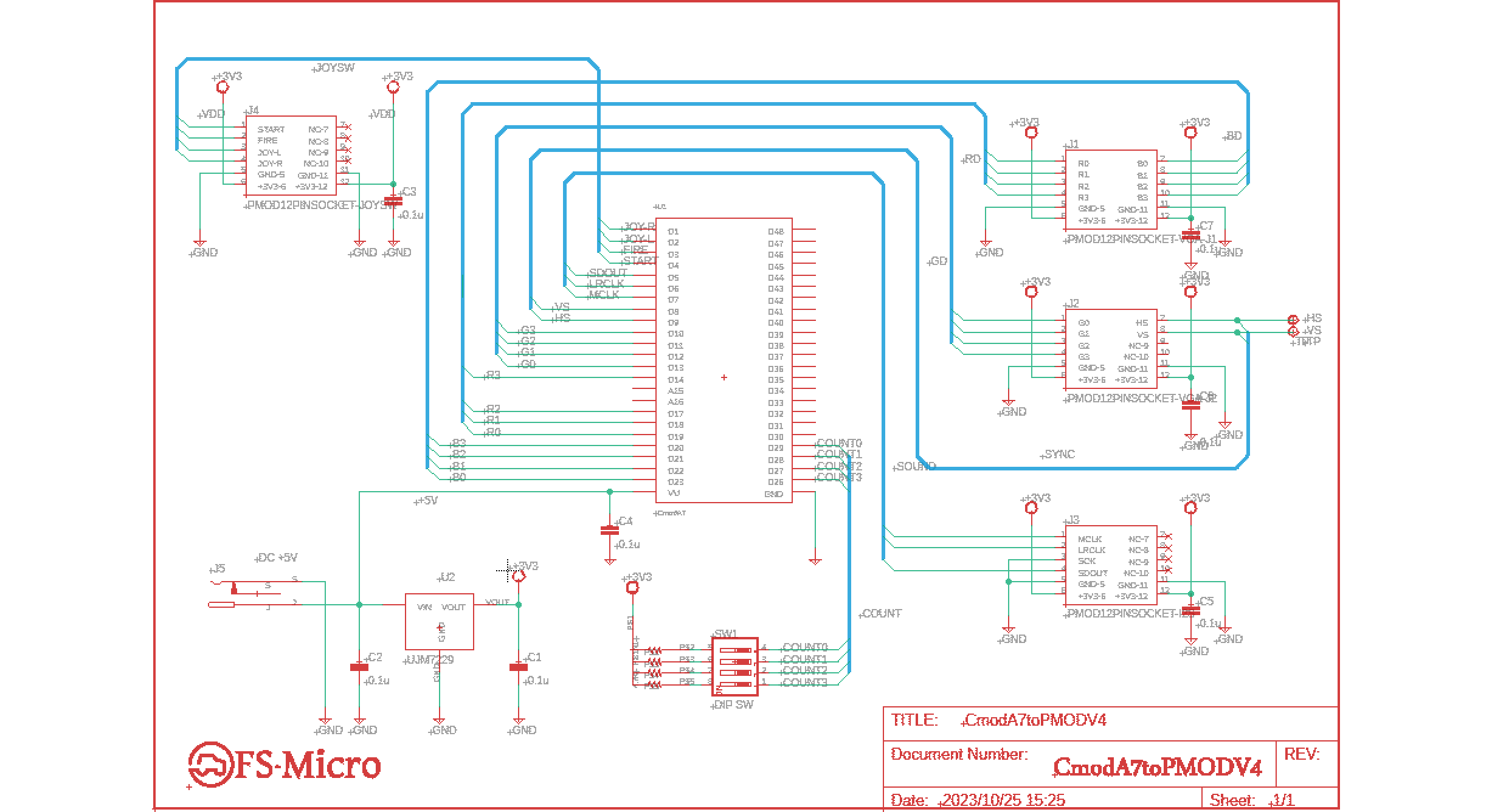
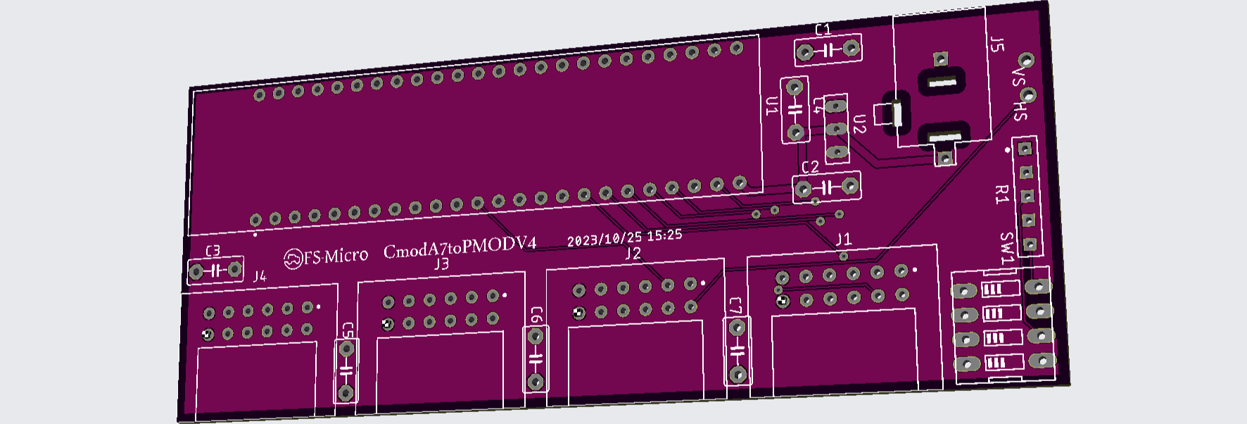
完成した回路図を図686.1に、レイアウト図を686.2に示します。ボードは仕様的に2層、80cm^2未満であるため、Eagleの無料版で設計することができました。

図%%.1
図686.1 CmodA7toPMODボード回路図

図%%.1
図686.2 CmodA7toPMODボードガーバー図

基板業者JLCPCBにおいて基板製造及び部品実装(PCBA)をオーダーしようと思いました。ところがSMT部品でないとアセンブリできないらしく、今回SMT部品が無いことから基板のみのサービスを利用しました。

表686.1 JLCPCB費用まとめ
内容 費用[USD]
基板製造費10枚 5.00
配送費(OCS) 1.98
合計 6.98

という結果でした。


左矢前のブログ 次のブログ右矢

Cmod A7の利用 (2)

posted by sakurai on October 25, 2023 #685

Eagleライブラリの作成

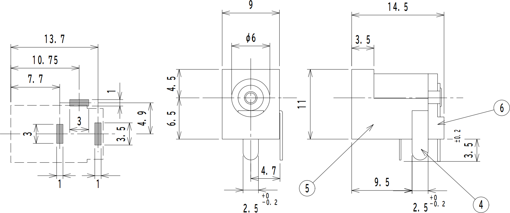
同様にDC Jackを登録します。以下にその基盤図及び実体図を示します。基盤穴をグレーで塗っています。

図%%.1
図685.1 Cmod A7ボード

EAGLEでこれを登録するには基盤図をfootprintに入力する必要があり、ライブラリを次のように作成します。

(1) symbolの編集画面において、

  • 部品外形をLayer=94 Symbolsで記述。
  • 適宜論理ピンを設定。
  • textでLayer=95 Namesとして">NAME"を追加。
  • textでLayer=96 Valuesとして">VALUE"を追加。

(2) footprintの編集画面において、

  • textでLayer=25 tNamesとして">NAME"を追加。
  • textでLayer=27 tValuesとして">VALUE"を追加。
  • Layer=20 Dimensionとする。
  • Widthを0とする。
  • Gridをmmにする。
  • ラインコマンドをクリックする。
  • 入力窓に、"(x, y)"と点を打つ。

以下"(x, y)"の繰り返しで図形を描きます。"20 Dimension"は外形線ですが、外形線の囲む内部に外形線があれば、囲まれた領域が穴になるという仕様です。ただし、上図は背面から見た図なので、上面から見た図はその裏返しとなります。

さらに、表面から背面に貫通する端子を背面で+5Vと接続させるため、背面のソルダーレジストを禁止とします。そのためには

  • 禁止したい領域をLayer=30 bStopとして矩形で囲む。

(3) deviceの編集画面において、

  • Edit ⇒ Addで作成したsymbolの読み込み
  • Edit ⇒ Packageで作成したfootprintの読み込み
  • 論理ピンと物理ピン(pad)の接続
  • prefixをクリックしてJと入力 (J1, J2, としたい場合)

特にここで挙げたsymbol画面とfootprint画面からのdevice画面への読み込みが直感的ではないので注意してください。


左矢前のブログ 次のブログ右矢

Cmod A7の利用

posted by sakurai on October 24, 2023 #684

Cmod A7

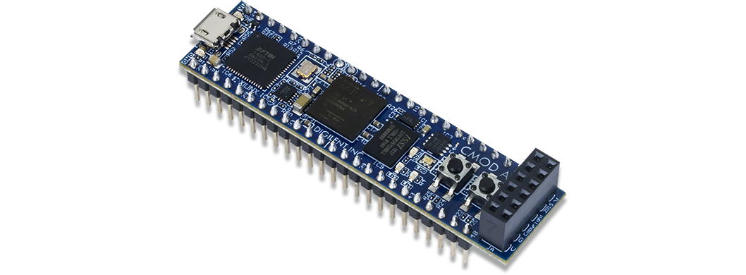
Cmod A7とはDigilentから販売されているArtix 7シリーズのFPGAの評価ボードで、その特長は小さくて安いことにあります。最近の世界的なインフレにより各種FPGAボードが値上がりしている中で、USD 99と最安の部類に入ります。

図%%.1
図684.1 Cmod A7ボード

小さくて安いFPGAボードですが、Arty A7-35ボードと同じFPGAを採用しているため、Space Invadersが動作するはずです。

CmodA7toPMOD

しかしながらArty A7ボードがPMODインタフェースを4個搭載しておりそのままPMOD-VGAやPMOD-Audioボードを接続できるのに対し、このボードはPMODが1個しかないため、PMODインタフェースを設計する必要があります。ただし、Ultra96と異なり端子電圧が3.3VであるためPMODと直接インタフェースでき、レベル変換ICが不要です。

そのためには変換ボード上に

  • Cmod A7ボード
  • PMODピンソケットコネクタ x 4
  • ACアダプタコネクタ(MJ-179PH)
  • 5V-3.3V電圧降下コンバータ(NJU7223F33)

等の部品を搭載する必要があります。

Eagleライブラリの作成

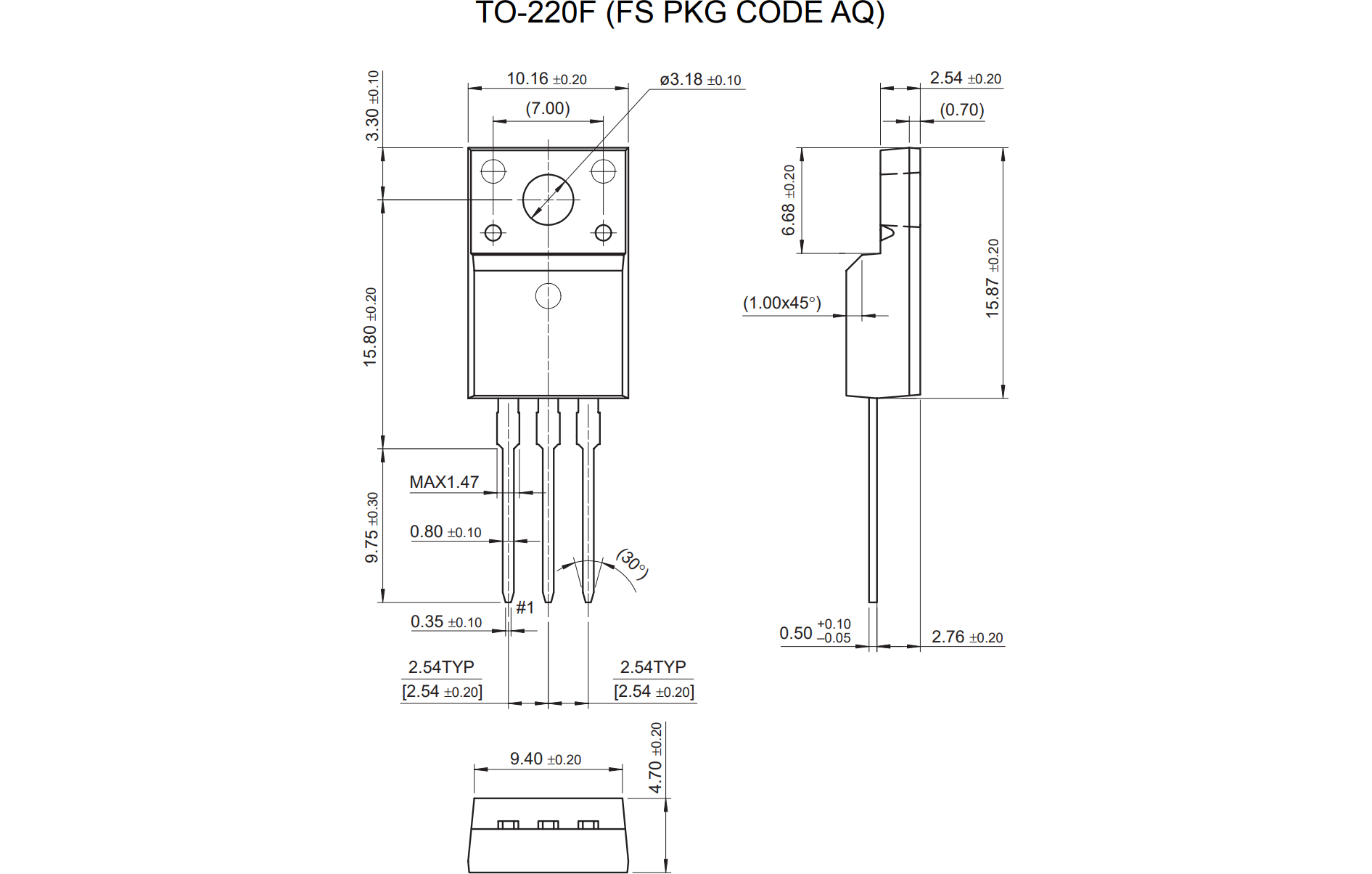
EAGLEでこれらを使用するにはシンボル図や基盤図をライブラリに登録する必要があります。例として電圧降下コンバータNJU7223F33の外形図を図684.2に示します。

図%%.2
図684.2 NJU7223F33外形図

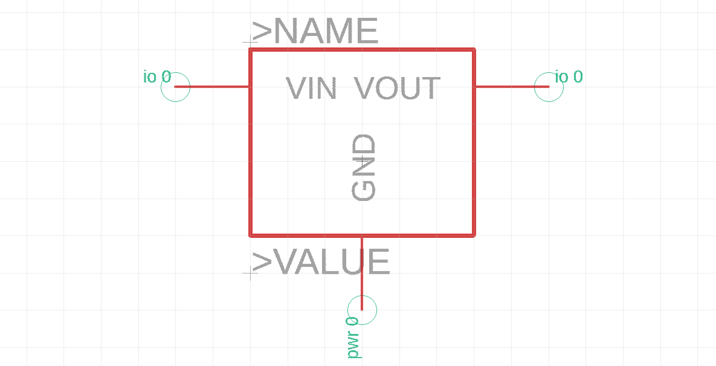
このシンボルとフットプリントを作成した図を以下に示します。

図%%.3
図684.3 NJU7223F33 symbol図

図%%.4
図684.4 NJU7223F33 footprint図

左矢前のブログ 次のブログ右矢

色変換回路 (5)

posted by sakurai on October 23, 2023 #683

BSVフォーラムで議論したところ、以下のような回答を順次頂きました。

  • 最初の一括でリターンを返すメソッドのほうが良い。が、メソッドの構造体を分割する手段は現状のBSVの文法にはない。従って手段としては2つあり、外側にverilogラッパーを設けて分割するか、BSVに新たな機能を追加するか。
  • 組み合わせ回路の関数を置いたらどうか?
  • clockとresetは、インタフェース外の端子を使えば消すことができる。
  • RDYが1にもかかわらずエラーになる件はbscのissueとして登録した。

組み合わせ回路の関数は良い方法だと思うので、今後色変換回路を組み込む場合にはそうしようと思います。

しかしながら今回は外付けのモジュールとしたため、clockとresetを消去する方法で行きたいと思います。提示されたソースは以下のとおり。

interface ColorConverter;
  (* result="RO" *)
  method Bit#(4) getRO();
  (* result="GO" *)
  method Bit#(4) getGO();
  (* result="BO" *)
  method Bit#(4) getBO();
endinterface

(* synthesize, always_ready, no_default_clock, no_default_reset *)
module mkColorConverter(
    (* port="RI" *) Bit#(1) r,
    (* port="GI" *) Bit#(1) g,
    (* port="BI" *) Bit#(1) b,
        ColorConverter ifc);

  method Bit#(4) getRO();
    return (case ({r, g, b})
      3'b000: 4'h0;
      3'b001: 4'h9;
      3'b010: 4'hd;
      3'b011: 4'h5;
      3'b100: 4'hc;
      default: 4'h0;
    endcase);
  endmethod

  method Bit#(4) getGO();
    return (case ({r, g, b})
      3'b000: 4'h0;
      3'b001: 4'h4;
      3'b010: 4'h8;
      3'b011: 4'hb;
      3'b100: 4'hc;
      default: 4'h0;
    endcase);
  endmethod

  method Bit#(4) getBO();
    return (case ({r, g, b})
      3'b000: 4'h0;
      3'b001: 4'h1;
      3'b010: 4'h4;
      3'b011: 4'h5;
      3'b100: 4'hC;
      default: 4'h0;
    endcase);
  endmethod
endmodule

メソッドを用いない入力方法があるようです。具体的にはinterfaceはメソッドを並べるため、interface定義外にポートを定義しています。

また、カラー0は非表示画面も示すため、変換せずに0のままと変更しました。

このソースから生成されるverilogコードはヘッダや定義文を除いて次のとおり。

module mkColorConverter(RI,
            GI,
            BI,
            RO,
            GO,
            BO);
  input  RI;
  input  GI;
  input  BI;

  // value method getRO
  output [3 : 0] RO;
  // value method getGO
  output [3 : 0] GO;
  // value method getBO
  output [3 : 0] BO;

  // signals for module outputs
  reg [3 : 0] BO, GO, RO;
  // remaining internal signals
  wire [2 : 0] x__h151;

  // value method getRO
  always@(x__h151)
  begin
    case (x__h151)
      3'b0: RO = 4'h0;
      3'b001: RO = 4'h9;
      3'b010: RO = 4'hD;
      3'b011: RO = 4'h5;
      3'b100: RO = 4'hC;
      default: RO = 4'h0;
    endcase
  end

  // value method getGO
  always@(x__h151)
  begin
    case (x__h151)
      3'b0: GO = 4'h0;
      3'b001: GO = 4'h4;
      3'b010: GO = 4'h8;
      3'b011: GO = 4'hB;
      3'b100: GO = 4'hC;
      default: GO = 4'h0;
    endcase
  end

  // value method getBO
  always@(x__h151)
  begin
    case (x__h151)
      3'b0: BO = 4'h0;
      3'b001: BO = 4'h1;
      3'b010: BO = 4'h4;
      3'b011: BO = 4'h5;
      3'b100: BO = 4'hC;
      default: BO = 4'h0;
    endcase
  end

  // remaining internal signals
  assign x__h151 = { RI, GI, BI } ;
endmodule  // mkColorConverter

verilogは正しく生成されています。


左矢前のブログ 次のブログ右矢

色変換回路 (4)

posted by sakurai on October 20, 2023 #682

試行錯誤した結果、always_readyは解決しました。WireでなくDWireを用いるとうまく消えることがわかりました。ソースにおいて修正点のみを示すと、

(* synthesize, always_enabled = "setInputs", always_ready = "getRO, getGO, getBO" *)

及び

    Wire#(Bit#(1)) r_reg <- mkDWire(?);
    Wire#(Bit#(1)) g_reg <- mkDWire(?);
    Wire#(Bit#(1)) b_reg <- mkDWire(?);

の2か所を修正するだけです。生成されたverilogはかなりスッキリしてきており、後は未使用のCLK及びRST_Nを削除する方法だけですが、(* no_default_clock, no_default_reset *) とすれば良いようです。

module mkColorConverter(CLK,
            RST_N,
            RI,
            GI,
            BI,
            RO,
            GO,
            BO);
  input  CLK;
  input  RST_N;

  // action method setInputs
  input  RI;
  input  GI;
  input  BI;

  // value method getRO
  output [3 : 0] RO;
  // value method getGO
  output [3 : 0] GO;
  // value method getBO
  output [3 : 0] BO;

  // signals for module outputs
  reg [3 : 0] BO, GO, RO;
  // remaining internal signals
  wire [2 : 0] x__h322;

  // value method getRO
  always@(x__h322)
  begin
    case (x__h322)
      3'b0: RO = 4'h9;
      3'b001: RO = 4'hD;
      3'b010: RO = 4'h5;
      default: RO = 4'hC;
    endcase
  end

  // value method getGO
  always@(x__h322)
  begin
    case (x__h322)
      3'b0: GO = 4'h4;
      3'b001: GO = 4'h8;
      3'b010: GO = 4'hB;
      default: GO = 4'hC;
    endcase
  end

  // value method getBO
  always@(x__h322)
  begin
    case (x__h322)
      3'b0: BO = 4'h1;
      3'b001: BO = 4'h4;
      3'b010: BO = 4'h5;
      default: BO = 4'hC;
    endcase
  end

  // remaining internal signals
  assign x__h322 = { RI, GI, BI } ;
endmodule  // mkColorConverter

左矢前のブログ 次のブログ右矢

色変換回路 (3)

posted by sakurai on October 19, 2023 #681

そもそもリターンメソッド(出力に相当する)が単一なのは、タイミング的に同時に12bitを読みだすからですが、これを4bitずつ3回にわけて読みだす形にします。すると、

interface ColorConverter;
  (* prefix="" *)
  method Action setInputs(
    (* port="RI" *) Bit#(1) r,
    (* port="GI" *) Bit#(1) g,
    (* port="BI" *) Bit#(1) b);
  (* result="RO" *)
  method Bit#(4) getRO();
  (* result="GO" *)
  method Bit#(4) getGO();
  (* result="BO" *)
  method Bit#(4) getBO();
endinterface

(* synthesize, always_enabled = "setInputs" *)
module mkColorConverter(ColorConverter);
    Wire#(Bit#(1)) r_reg <- mkWire;
    Wire#(Bit#(1)) g_reg <- mkWire;
    Wire#(Bit#(1)) b_reg <- mkWire;

  method Action setInputs(Bit#(1) r, Bit#(1) g, Bit#(1) b);
    r_reg <= r;
    g_reg <= g;
    b_reg <= b;
  endmethod

  method Bit#(4) getRO();
    return (case ({r_reg, g_reg, b_reg})
      3'b000: 4'h9;
      3'b001: 4'hD;
      3'b010: 4'h5;
      3'b100: 4'hC;
      default: ?;
    endcase);
  endmethod

  method Bit#(4) getGO();
    return (case ({r_reg, g_reg, b_reg})
      3'b000: 4'h4;
      3'b001: 4'h8;
      3'b010: 4'hB;
      3'b100: 4'hC;
      default: ?;
    endcase);
  endmethod

  method Bit#(4) getBO();
    return (case ({r_reg, g_reg, b_reg})
      3'b000: 4'h1;
      3'b001: 4'h4;
      3'b010: 4'h5;
      3'b100: 4'hC;
      default: ?;
    endcase);
  endmethod
endmodule

このソースからは以下のverilogが生成されます。

module mkColorConverter(CLK,
            RST_N,
            RI,
            GI,
            BI,
            RO,
            RDY_getRO,
            GO,
            RDY_getGO,
            BO,
            RDY_getBO);
  input  CLK;
  input  RST_N;
  // action method setInputs
  input  RI;
  input  GI;
  input  BI;
  // value method getRO
  output [3 : 0] RO;
  output RDY_getRO;
  // value method getGO
  output [3 : 0] GO;
  output RDY_getGO;
  // value method getBO
  output [3 : 0] BO;
  output RDY_getBO;
  // signals for module outputs
  reg [3 : 0] BO, GO, RO;
  wire RDY_getBO, RDY_getGO, RDY_getRO;
  // remaining internal signals
  wire [2 : 0] x__h322;
  // value method getRO
  always@(x__h322)
  begin
    case (x__h322)
      3'b0: RO = 4'h9;
      3'b001: RO = 4'hD;
      3'b010: RO = 4'h5;
      default: RO = 4'hC;
    endcase
  end
  assign RDY_getRO = 1'b1 ;
  // value method getGO
  always@(x__h322)
  begin
    case (x__h322)
      3'b0: GO = 4'h4;
      3'b001: GO = 4'h8;
      3'b010: GO = 4'hB;
      default: GO = 4'hC;
    endcase
  end
  assign RDY_getGO = 1'b1 ;
  // value method getBO
  always@(x__h322)
  begin
    case (x__h322)
      3'b0: BO = 4'h1;
      3'b001: BO = 4'h4;
      3'b010: BO = 4'h5;
      default: BO = 4'hC;
    endcase
  end
  assign RDY_getBO = 1'b1 ;
  // remaining internal signals
  assign x__h322 = { RI, GI, BI } ;
endmodule  // mkColorConverter

出力ポートの形は狙い通り4bit×3個となりました。しかしながら、問題点は生成されたコメントにもあるように、

// Ports:                                                                   
// Name                         I/O  size props                             
// RO                             O     4                                   
// RDY_getRO                      O     1 const                             
// GO                             O     4                                   
// RDY_getGO                      O     1 const                             
// BO                             O     4                                   
// RDY_getBO                      O     1 const                             
// CLK                            I     1 unused                            
// RST_N                          I     1 unused                            
// RI                             I     1                                   
// GI                             I     1         
  1. RDY信号が定数でalways_readyを示す
  2. CLK, RST_Nが未使用

であることから両者とも削除可能です。入力のenableは always_enabled = "setInputs" で示すように削除することができたのですが、always_readyを指定してもエラーとなり、RDY信号を削除することができませんでした。

さらに、no_default_clock, no_default_reset によりCLKとRST_Nを削除できる場合もあるようですが、この場合はエラーが発生してできませんでした。この2点が疑問です。


左矢前のブログ 次のブログ右矢

色変換回路 (2)

posted by sakurai on October 18, 2023 #680

このソースから生成されたverilogファイルは以下のようになります。先頭のコメントやifdef文等を省略したソースを示します。

module mkColorConverter(RI,
            GI,
            BI,
            OUT);
  // value method mapColor
  input  RI;
  input  GI;
  input  BI;
  output [11 : 0] OUT;

  // signals for module outputs
  reg [11 : 0] OUT;

  // remaining internal signals
  wire [2 : 0] x__h134;

  // value method mapColor
  always@(x__h134)
  begin
    case (x__h134)
      3'b0: OUT = 12'd2369;
      3'b001: OUT = 12'd3460;
      3'b010: OUT = 12'd1461;
      default: OUT = 12'd3276;
    endcase
  end

  // remaining internal signals
  assign x__h134 = { RI, GI, BI } ;
endmodule  // mkColorConverter

図%%.1
図680.1 色変換回路

問題は以下のようにstructで3つのデータを構造化しているにも関わらず、12ビット出力ポートが1個生成されてしまうことです。構造体メンバを取り出す方法がありません。

typedef struct {
  Bit#(4) ro;
  Bit#(4) go;
  Bit#(4) bo;
} ColorOutputs deriving (Bits);

これを4bitの3つの出力ポートとしたいわけです。

不思議なことにBSVの世界から離れてverilogだけでなんとかしようとして手修正によりポートを3つに分けてみたのですが、思ったようにはなりませんでした。例えばverilogを

module mkColorConverter(RI,
                    GI,
                    BI,
                    RO,
                    GO,
                    BO);
  // value method mapColor
  input  RI;
  input  GI;
  input  BI;
  output [3 : 0] RO;
  output [3 : 0] GO;
  output [3 : 0] BO;

  // signals for module outputs
  wire [3 : 0] RO = OUT[11:8];
  wire [3 : 0] GO = OUT[7:4];
  wire [3 : 0] BO = OUT[3:0];
  reg [11: 0] OUT;

のように手修正しても、以下の図のような回路となってしまいました。ポート名は良いのですが、ポート番号が思ったように付いてくれません。

図%%.2
図680.2 色変換回路

いちいち手修正するのも嫌なので、BSVで可能な方法を探ります。


左矢前のブログ 次のブログ右矢

色変換回路

posted by sakurai on October 17, 2023 #679

単なる組み合わせ回路による拾変換回路についてかなりトラブルが有ったので、備忘のために記します。

まず、設計したい色変換回路は以下のようなものです。入力はRI, GI, BIのそれぞれ1ビット、出力はRO[3:0]、GO[3:0]、BO[3:0]の3 * 4ビットの回路です。原色を中間色に変換する、2^12(=4096)色中の2^3(=8)色を表示する固定カラーパレットとも言えます。

図%%.1
図679.1 色変換回路

最初に次のようなプログラムをChatGPTの助けを借りて作成しました。

typedef struct {
  Bit#(4) ro;
  Bit#(4) go;
  Bit#(4) bo;
} ColorOutputs deriving (Bits);

interface ColorConverter;
  (* result="OUT" *)
  (* prefix="" *)
  method ColorOutputs mapColor(
    (* port="RI" *) Bit#(1) r,
    (* port="GI" *) Bit#(1) g,
    (* port="BI" *) Bit#(1) b);
endinterface

(* synthesize, always_ready = "mapColor", no_default_clock, no_default_reset *)
module mkColorConverter(ColorConverter);
  method ColorOutputs mapColor(Bit#(1) r, Bit#(1) g, Bit#(1) b);
    Bit#(4) ro = (case ({r, g, b})
      3'b000: 4'h9;
      3'b001: 4'hD;
      3'b010: 4'h5;
      3'b100: 4'hC;
      default: ?;
    endcase);

    Bit#(4) go = (case ({r, g, b})
      3'b000: 4'h4;
      3'b001: 4'h8;
      3'b010: 4'hB;
      3'b100: 4'hC;
      default: ?;
    endcase);

    Bit#(4) bo = (case ({r, g, b})
      3'b000: 4'h1;
      3'b001: 4'h4;
      3'b010: 4'h5;
      3'b100: 4'hC;
      default: ?;
    endcase);

    return ColorOutputs {ro: ro, go: go, bo: bo};
  endmethod
endmodule

左矢前のブログ 次のブログ右矢


ページ: