|
27 |
BSVの階層生成とシミュレーション (4) |
Verilogシミュレーション
これにより、モジュールにクロックとリセットが最上位に自動的に生成され、モジュールとのI/Fが正しく接続されたので、iverilgにより全体のverilogシミュレーションモデルを作成し、verilogシミュレーションを実行します。
$ iverilog top.v testFSM.v -o testFSM.exe
これを実行すると以下の表示が得られ、正しくFSMが動作したことが分かります。
$ ./testFSM.exe
VCD info: dumpfile testFSM.vcd opened for output.
Counter =   0, State: IDLE
Counter =   1, State: STEP1
Counter =   2, State: STEP1
Counter =   3, State: STEP1
Counter =   4, State: STEP1
 (中略)
Counter =  96, State: STEP1
Counter =  97, State: STEP2
Counter =  98, State: STOP
Counter =  99, State: IDLE
Counter = 100, State: IDLE
Done
同時にダンプファイルtestFSM.vcdが得られるので、GTKWave波形ビュワーにより以下のようにVCDを開き、波形を確認します。
$ gtkwave -A testFSM.vcd

GTKWave Analyzer v3.3.107 (w)1999-2020 BSI

[0] start time.
[1010] end time.
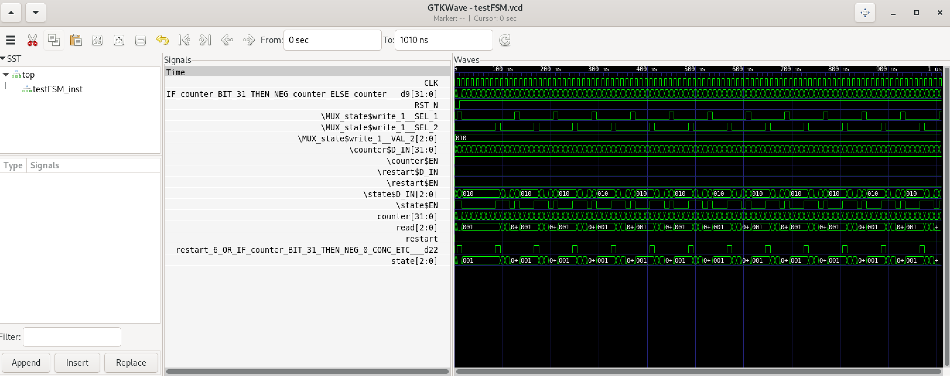
設定を^sにより同名のtestFSM.gtkwに入れておくと、上記"-A"フラグにより起動と同時に波形まで開くことができます。

Leave a Comment