|
2 |
ISO 26262のFTAに関する論文 (11) |
参照論文は完全冗長系のEPSを題材としているので、本ブログでもこのEPSシステムのPMHFを計算することにします。なお本論文において車両寿命は15,000時間、2nd SMの検査時間は1時間にしているようです。
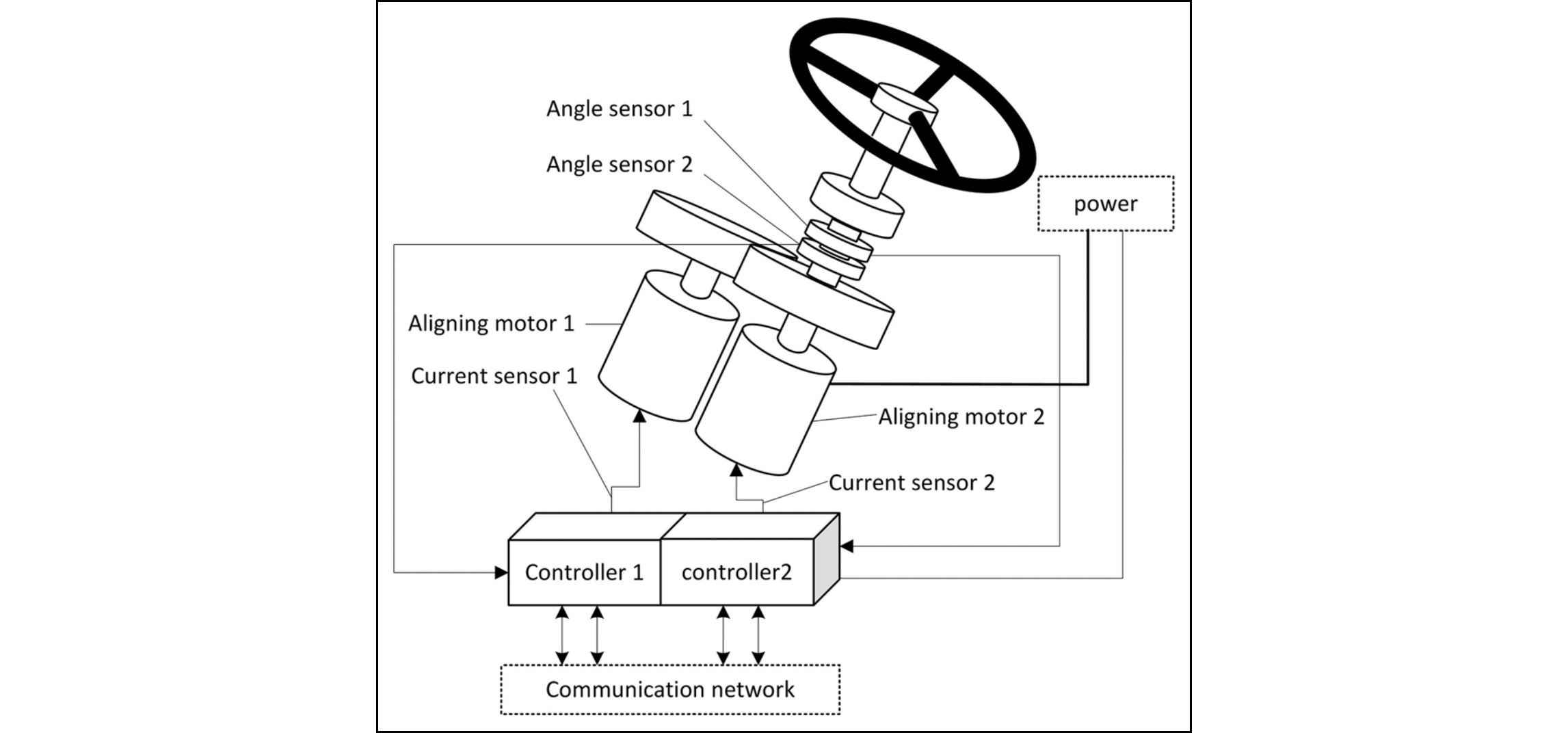
図212.1にEPSシステム構成図を示します。

このEPSシステムのRBDを図212.2に示します。

表212.1にRBD中のエレメント記号とエレメント名等を示します。
| エレメント記号 | エレメント名 | 故障率[FIT] | SM記号 | SM名 | DC[%] |
|---|---|---|---|---|---|
| P | Power Module | 233 | None | None | 0 |
| MCU | Micro Control Unit | 818 | SM4 | Self test | 99 |
| D | Motor Drive Module | 109 | SM2 | Output test | 99 |
| I | Failure Isolation Module | 599 | SM1 | Input test | 60 |
| M | Aligning Motor | 1000 | SM5 | Motor sensing test | 90 |
| SC | Current Sensor | 1000 | SM2 | Output test | 99 |
| CA | CAN Communication Module | 51 | SM1 | Input test | 60 |
| SA | Angle Sensor | 1000 | SM3 | Sensor compare | 99 |
この表のSMは、通常は1st order SMとしてVSG抑止のためのSMと位置付けられます。ところが、このように冗長の内部(冗長チャネルを構成するエレメントに対するSM)に存在する場合、冗長の相手チャネルが1st order SMとなります。従って、表中のSMは、それによりVSG抑止される場合のLF防止のSM、つまり2nd order SMと位置付けられます。
例えばあるエレメントが故障しても冗長構成であれば、相手チャネルが動作しているので、VSGは抑止されます。ところが冗長系は、故障の検出は一切行わないため、そのエレメント故障の100%がLFとなります。そのエレメントに故障検出のためのSMがあれば、LF防止のためのSM、つまり2nd order SMとなることがわかります。

Leave a Comment